In this article:
Intelligent Power Management with Axiomtek
Axiomtek has committed to providing reliable power protection solutions for its industrial PC products, which are deployed in mission critical environments for applications such as on-board mass transit surveillance, factory automation or rugged outdoor applications where highly reliable computers are the key to the continuity of operations.
Axiomtek has committed to providing reliable power protection solutions for its industrial PC products, which are deployed in mission critical environments for applications such as on-board mass transit surveillance, factory automation or rugged outdoor applications where highly reliable computers are the key to the continuity of operations. In many industrial processes, the continuity of power supply is required 24/7. The power source needs to be regulated and protected to prevent loss of important information or costly downtime, for example in a production line environment. The computers used to control the operations should be ready to predict and respond quickly to a sudden power failure. Many of Axiomtek’s embedded motherboards and systems offer the IPM feature to combat power fluctuation issues. The Intelligent Power Management (IPM) functionality is integrated into the CPU motherboard or offered as a separate module. In this article, the focus will be on the general hardware structure and functionality of the IPM unit utilized in transportation embedded systems designed by Axiomtek. We will also showcase the ease of use of the system’s utilities, e.g. setting changes through the BIOS or OS.
Intelligent Power Management of Axiomtek’s tBOX Products
One example of Axiomtek products that contain the IPM module is the tBOX324-894-FL. The module is designed to handle a 9 – 36V wide range power input while ensuring that it delivers a stable and safe 12V power supply to the CPU motherboard. The Axiomtek IPM’s power input includes an additional Accessories/Ignition ACC input pin, a standard power switch pin used in various transportation applications.
The IPM module works as seen in Figure 1 below:

Its ability to control the voltage and deliver stable 12V power can be explained by means of 3 main operational blocks.
1. Input Voltage Protection Block
In industrial applications where the power supply voltage is not stable or is provided by a battery, it is important for the controller to be able to operate with a wider range of voltage inputs than the conventional, fixed 12V or 24V DC. In most transportation applications, the main source of power is the battery. When a battery discharges over time, the voltage level starts degrading. At some point, it will no longer be able to power the system. It is therefore important to detect the instability of the voltage and predict the pace of battery drainage. With the IPM, an alert system is put in place to prevent operational failure due to power instability issues. The controller can predict the inevitable shut down of the system. Subsequently, it can take loss prevention steps such as securely saving important data and information created by all running programs, closing the programs and eventually shutting down the system safely.
The Input Voltage Protection Block can be divided into three major sub-blocks:
A. Reverse Voltage Protection
Reverse voltage is a common concern for industrial applications. In many instances, the input power can be delivered without the standard power connectors through bare wires reworked to fit into a Phoenix-type terminal connector. In such a configuration, the probability of confusing or mixing the polarity of the power input is high, resulting in major damage to the system and rendering it useless in a matter of seconds. There are several ways to prevent this from happening. A reverse voltage protection can include the use of diodes, a type of passive semiconductor device that can block the current flow in one direction; the use of active semiconductor devices such as bipolar junction transistors (BJTs); or the use of metal oxide semiconductor field effect transistors (MOSFETs) that can be used to regulate the system’s power access when a reverse voltage input occurs. Depending upon the system requirements, the solution can be composed of just one diode, or a MOSFET, or a diode and a few passive components. A more complex solution can include an integrated circuit (IC) controller that will regulate the input voltage and block its access to the system if a reverse voltage is detected. This can be done through controlling the gate/threshold voltage of the MOSFETS.
B. Under-Voltage and Over-Voltage Protection
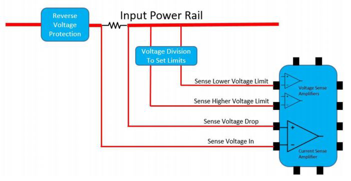
Under- and over-voltage protection is accomplished by setting limits, sensing the upper and lower limit settings, and feeding the information to the power protection controller chip for any required action. See Figure 2 below for a block diagram of how the Power Controller IC receives information about the input voltage.
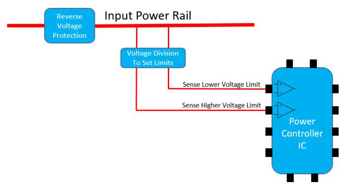
For example, the limit for low voltage is set to 9V while the high voltage limit is set to 36V. The voltage is fed into one of the inputs of the IC that controls the under-voltage level. If the feedback voltage detected is lower than a certain reference voltage level inside the IC (for example 1.25V), then the output of the power protection IC will be switched off. The over-voltage protection works the same way. For example, if the feedback voltage is higher than 1.25V, the output voltage of the controller circuit will turn off or not turn on.
C. Over-Current Protection
Over-current protection is achieved by placing a low value resistor (in the milli Ohms range) in series between the load and input voltage. Both ends of the resistor Rsense are inputs to the current sensing amplifier (see Figure 3 below). If the current through the resistor increases the voltage level beyond the set voltage drop and the Voltage In, or if it reaches the maximum defined limit set by the controller chip – e.g. 50mV, the IC will shut off the power supply to the system. The amount of current allowed to pass is dependent on the resistor value. If the resistor value is 1 milliOhm and the maximum voltage of the amplifier input is 50mV, then the allowed current will be 50mV/1milliOhm = 50A. The current limit can be reduced by adjusting the sensing resistor. For example, if the desired current limit is 10A, then the sensing resistor value must be changed to 5mOhm: 50mV/5milliOhm = 10A.
2. MCU Block
The MCU block acts as the brain of the IPM module. It receives signals from different blocks that can indicate that certain actions have taken place. It can also send signals that will have specific meanings for the receiving blocks.
Some of the signals that the MCU receives (see Figure 1) are Input Power OK, ACC Interrupt and Universal Asynchronous Receiver/Transmitter (UART) signals that can change the timer settings and tell the MCU that information has been saved in the computer before shutdown. Some of the signals that the MCU is communicating back are Unit ON and OFF, Output Voltage (VCC OUT) and communications to the PC via UART about the IPM settings, etc. The above are just basic examples of how the system works and more complex communication is possible on the IPM module.
The Input Power OK signal, received from the Power Protection Block, is usually a digital HIGH/LOW signal that indicates the power input is compliant with all of the voltage and current level requirements of the system. If everything is fine with the power input, the MCU will send a digital signal to the voltage regulator to allow the activation of the 12V power input of the CPU motherboard. It will also send a signal to the CPU through Power Supply On (PSON) to turn it on. The system is intelligent with the ability to prioritize. If the Input Power OK signal indicates that everything is fine with the input voltage but the ACC Interrupt is not ON, the system will still stay turned off.
The MCU is capable of telling the system CPU through UART serial communication that it is time to turn off the system. It can delay the shutdown process to allow the computer to stop its ongoing actions and save important data before turning off the system. The CPU itself can communicate with the MCU and change some settings, such as the delays before turning the system ON and OFF.
The MCU is in charge of the management of the system’s power source and it plays a crucial role in providing secure power management to the main system.
3. Voltage Regulation Block
The Voltage Regulation Block is used to maintain a stable voltage level and is one of the more complex blocks designed to deliver an optimum level of low-noise, stable and fixed output voltage. The main purpose of the Voltage Regulation Block is to provide fixed voltage output, e.g., 12V, when the input voltage varies from 9 – 36V. There are several topologies including Buck, Boost, Buck-Boost, isolated and non-isolated topologies. Designing each voltage regulation circuit topology requires different approaches. The process begins with a schematic design that includes thermal considerations of heat dissipation, especially in high current and high power systems.
UEFI
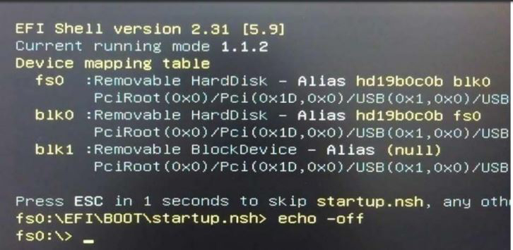
The Axiomtek PMU comes with software that allows the user to manage some of the settings through its BIOS or in-OS application interfaces. The process requires a USB bootable flash drive with the UEFI files uploaded before booting the system. Once the USB drive is ready, the user can attach the flash drive to the system, and through the BIOS settings’ boot section, select it to be the priority boot device. Once this step is completed, the user can restart the system and have it booted using the USB drive.
In UEFI shell mode, enter PSU.efi and press enter as shown in the Figure 4 below:
Next, in the power management settings, all of the important information regarding the power supply status can be found as seen below:
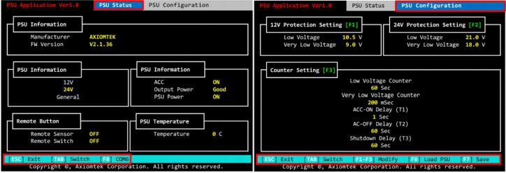
Use Tab to navigate through both pages. In the PSU Configuration, some modifications can be made to parameters such as voltage levels and delay times, etc
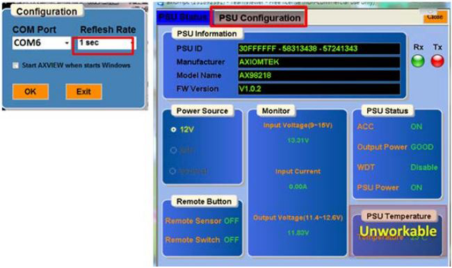
The setting parameters can also be manipulated through the in-OS utility for Windows. After running the executable file, select the COM port where the IPM unit is found. The settings window will appear as seen below and changes can be made.
ACC INTERRUPT – Transportation Systems
The abbreviation ACC comes from the word “Accessories” and was first introduced in cars as one of the positions on the ignition switch. When a car key is inserted into an ignition switch and turned to the left, the ACC circuit is turned on. This allows you to have the power supply to operate the radio, the windows and other accessories. Nevertheless, it does not turn on the vehicle’s fuel pump and other engine controls. The battery power is saved for use when the vehicle is started. For commercial vehicles, there is a set list of peripheral circuits that use battery power in the ACC mode. In other industrial transportation fields, the number of related applications can be higher than those of commercial vehicles. Additional computers may be required to control the additional devices, e.g. cameras, bill scanning devices, sensors for door opening and closing, etc.
Axiomtek tBOX Power Connector
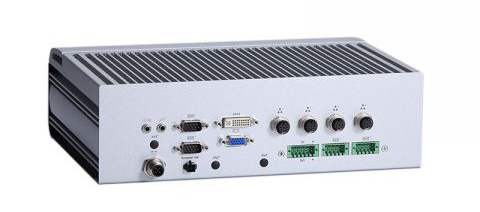
The tBOX products include the ACC pin at the power input that acts as the power ON/OFF switch. For example, in the tBOX324-894-FL the photo below shows the green Phoenix type connector at the bottom left. It is the main power input. The tBOX324-894-FL can accept a range of voltage inputs of 9 – 36V. Pin + is connected to voltages between 9 and 36V
Pin – is usually the GND (0V) or the lowest reference voltage level
Pin ACC – the middle pin is either the ACC ignition pin or the G (chassis ground) pin
This is possible because at the time when the car key is turned OFF, the battery power is still available at the power connector and the tBox is not completely disconnected from the power source. The power control unit has time to tell the computer to shut down and enter the sleep mode to protect the battery from draining while the car is turned OFF.
Applications
Axiomtek offers many high quality transportation-certified solutions that have the Intelligent Power Management feature. Below are two examples of applications for which the feature helps provide operational stability in mission critical environments.
Axiomtek’s tBOX324-894-FL is one of the latest products introduced in the transportation embedded systems product line (tBOX). This feature-rich transportation-certified embedded system offers the power protection feature plus enhanced flexibility and customizability with a variety of I/O connections. It supports industry standard USB, COM, CAN, Ethernet and Digital I/O communication interfaces and display interfaces include VGA and DVI-I. There are multiple options for the power input voltage range and for connector types including Phoenix and M12. With scalable, powerful options of the Intel 7th Generation Core™ i7, i5 or i3 CPUs, the tBOX324-894-FL is eminently suitable for complex mission critical projects.

About Assured Systems
Assured Systems is a leading technology company offering high quality and innovative applied computing solutions to the embedded, industrial, and digital-out-of-home markets across the world. Headquartered in Stone, England and with offices in North America, our reach is truly global. Our impressive product portfolio includes a full range of Fanless Embedded Computer Systems, Digital Signage & Multimedia Computer Systems, Touchscreen Panel PCs, Human Machine Interfaces, Vehicle Mount Computers, Rackmount Computer Systems, Single Board Computers, Rugged Laptops & Tablets.

